What you need to know about the Clean-In-Place (CIP) System
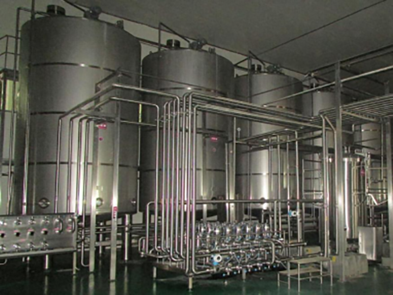
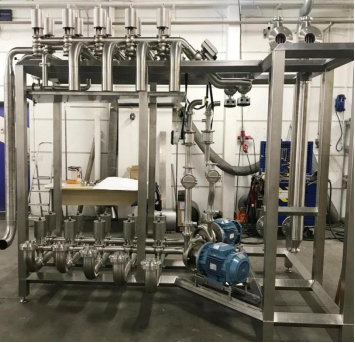
YoLong CIP Station is designed to clean brewery equipment, tanks and piping in breweries, wineries, distilleries, dairies, and other beverage and food facilities. At YoLong, we install the CIP station with two key elements -The Clean-In-Place (CIP) System Skid and Valve Matrix. Let us introduce you to the main components of the system:
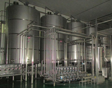
- CIP Skid
The tanks and the platform are mounted as one skid. It contains the following equipment:
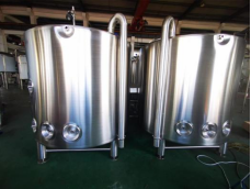
- Tanks with instrumentation
- Circulation circuit
- Chemical inlet valves
- Manual drain valve
- The vessels and platform have adjustable feet
Materials of Construction – Sanitary Piping
- 316SS tubing and fitting, polished ID/OD
- Tri-Clamp or Union Type Fittings
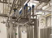
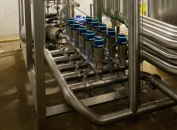
- Valve Matrix
A valve matrix is made where the valves, instruments and piping for the following equipment is mounted:
- Water supply
- CIP turn and return line
- Supply pumps
- Heat exchangers
- The skid shall have adjustable feet.
Materials of Construction – Sanitary Piping
- 316SS tubing and fitting, polished ID/OD
- Tri-Clamp or Union Type Fittings
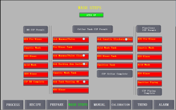
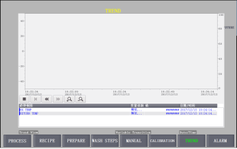
- Control Programming
Controls programming (PLC and HMI) for the CIP Skid to perform routing of the CIP solutions. The system is based on a configurable design allowing for a customized cleaning process to be set up by the operator. Configuration screen will allow the operator to specifically setup a cleaning sequence based on tank operation time, temperature, and concentration of solutions.
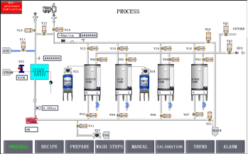
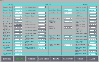
The programming of the automatic and manual operating capabilities into the CIP System is part of our installation. The automatic system will be controlled via designated CIP circuits to be selected by system operators with system safety interlocks. The manual operation of the system will allow for singular valve pulsing, direct pump control with ON/OFF and speed modifications capabilities.
Want to know more about the CIP system and process? Contact our friendly support or sales rep and they would love to help you.
Additional FAQs for the Clean-In-Place (CIP) System
1) What are typical CIP cycles and setpoints for brewery tanks?
- Common sequence: Pre-rinse (ambient, 5–10 min) → Alkaline wash (1–2% caustic at 60–75°C, 15–30 min) → Intermediate rinse (ambient, to conductivity setpoint) → Acid wash for beerstone (0.5–1% nitric/phosphoric at 50–60°C, 10–20 min, as needed) → Sanitizer (PAA 100–200 ppm, 5–15 min, no-rinse). Adjust per soil load and OEM specs.
2) How do I verify my CIP is actually cleaning effectively?
- Use riboflavin coverage tests for spray devices, monitor conductivity/temperature/flow/pressure, and validate with ATP swabs or rapid micro where applicable. Document pass/fail criteria in your SOP and trend results.
3) What flow and pressure do I need for CIP spray balls?
- Most static spray balls require 1.5–2.5 bar (22–36 psi) at the ball and sufficient flow to achieve 1.2–1.5 m/s line velocity; rotary devices have OEM-specific ranges. Always size the CIP pump and return lines to maintain target pressure at the device, not just at the pump discharge.
4) How can I reduce water and chemical use in my Clean-In-Place (CIP) System?
- Implement conductivity-based phase termination, reuse final rinse as next pre-rinse, install heat recovery on caustic/return loops, insulate CIP tanks/lines, and use VFDs to modulate pump speed. Track water-to-CIP ratio and chemical concentration drift.
5) What documentation and compliance records should a modern CIP include?
- Calibration records for probes (conductivity, temperature, flow), batch reports with time/temp/conductivity/flow/pressure traces, chemical lot/COA, corrective actions for deviations, and annual validation (coverage and micro). Align with BA, EHEDG, or 3-A guidance as applicable.
2025 Industry Trends: Clean-In-Place (CIP) System
- Sensor-driven optimization: Wider use of conductivity and temperature profiling with auto phase termination reduces utilities 10–20%.
- Energy recovery: Plate heat exchangers on CIP return loops and tank insulation becoming standard to cut heat loss.
- Smart skids: PLC/HMI with cloud logging, electronic batch records, and automated interlocks tied to valve matrices.
- Hygiene by design: More crevice-free manifolds, orbital welds, and validated spray device coverage to meet retailer audits.
- Chemicals and safety: Increased adoption of lower-foam caustics and PAA monitoring sensors; better splash/ventilation controls.
2025 CIP Benchmarks and Specifications
| Parameter | Typical 2025 Target | Notes |
|---|---|---|
| Conductivity control | ±3–5% of setpoint | Auto phase change on plateau |
| Alkaline wash temp | 60–75°C | Based on soil/fouling |
| Line velocity | ≥1.5 m/s (5 ft/s) | For effective scouring |
| Spray device pressure | 1.5–2.5 bar at device | Verify at the ball |
| Water reduction via reuse | 10–25% | Pre-rinse recovery |
| Chemical savings (sensor control) | 8–18% | Conductivity-driven dosing |
| Record retention | ≥2 years of batch logs | Digital preferred |
| Lead time for CIP skids | 6–12 weeks | Custom valve matrices longer |
Sources: Brewers Association (BA) quality/safety resources 2024–2025; MBAA Technical Quarterly; EHEDG and 3-A guidance; vendor spec sheets and ProBrewer practitioner reports
Latest Research Cases
Case Study 1: Conductivity-Controlled Phase Termination Cuts Utilities (2025)
Background: A 30-bbl brewery ran time-based CIP, leading to overcleaning and high water/chemical costs.
Solution: Upgraded PLC/HMI to enable conductivity-driven phase changes, installed calibrated temp/flow sensors, and reused final rinse as next pre-rinse.
Results: Water use per CIP cycle down 19%; caustic usage down 14%; average cycle time reduced by 12 minutes; no increase in ATP fail rates.
Case Study 2: Spray Coverage Validation Improves Micro Outcomes (2024)
Background: Intermittent post-CIP micro positives on a bright tank and two FVs.
Solution: Performed riboflavin coverage tests, adjusted spray ball sizing/pressure, and replaced one undersized static ball with a rotary jet head; updated SOPs and trained staff.
Results: 100% coverage achieved; three-month trend showed zero post-CIP micro positives; CIP pump VFD tuning lowered energy use ~7%.
Expert Opinions
- Dr. Martin Wiedmann, Professor of Food Safety, Cornell University
“Verification is non-negotiable. Coverage testing and electronic batch records transform CIP from a checklist into a validated process.” - John Mallet, Brewing Operations Consultant
“Size pumps and return lines for the pressure at the spray device—not just pump nameplate. Many ‘dirty’ tanks are simply under-pressured.” - Laura Ulrich, Senior Brewer and Pink Boots Society leader
“Simple wins: calibrated probes, clear setpoints, and reuse of rinses. Teams follow SOPs when the system makes the right way the easy way.”
Practical Tools and Resources
- Brewers Association – Quality and safety resources: https://www.brewersassociation.org
- Master Brewers Association of the Americas (MBAA) – CIP webinars, TQ papers: https://www.mbaa.com
- EHEDG – Hygienic design guidelines: https://www.ehedg.org
- 3-A Sanitary Standards – CIP-related equipment standards: https://www.3-a.org
- ProBrewer – CIP sizing, valve matrix discussions: https://www.probrewer.com
- NIST – Calibration guidance for process sensors: https://www.nist.gov
Sources and further reading:
- Brewers Association 2024–2025 QA and safety briefs
- MBAA Technical Quarterly on CIP validation and sensor control
- EHEDG/3-A guidance on hygienic equipment design
- Vendor application notes for spray devices, pumps, and PLC/HMI integration
Last updated: 2025-09-08
Changelog: Added 5 CIP-specific FAQs; inserted 2025 benchmark/spec table; provided two recent case studies; included expert viewpoints; compiled practical tools/resources with authoritative links.
Next review date & triggers: 2026-01-15 or earlier if BA/EHEDG/3-A publish new CIP validation guidance, major sensor/chemical innovations emerge, or utility cost shifts change optimization best practices.
Share this entry
Interested in learning more about Brewing Systems including additional details and pricing information? Please use the form below to contact us!
YOLONG BREWERY EQUIPMENT FAQS
- Commercial Brewery / Craft Brewery / Microbrewery / Nanobrewery
- What is The Difference Between Craft Beer and Industrial Beer?
- The Bespoke Differences In Custom Brewing Systems
- Everything You Need to Know About Kettle Souring
- How to Choose Brewing Equipment for Your business?
- How To Choose The-Best Partner To Build Your Commercial Microbrewing System?
- Two Detection Sensors That You Need To Use In Your Brewhouse System
- Remote Control Applications in Brewing Equipment/How does it work?
- How To Clean Your Brand New Brewery Tanks?